Thermostat Update Version 3.2

I suppose it’s about time to let you know about the multitude of changes in my thermostat. If you’ve been following along, you might be surprised that I’ve jumped all the way from Version 2.0 to Version 3.2, but that’s just how drastic the updates have been. You can read about version 1 here, and the version 2 update here, if you want the backstory.

Is that a Photon in your pocket?

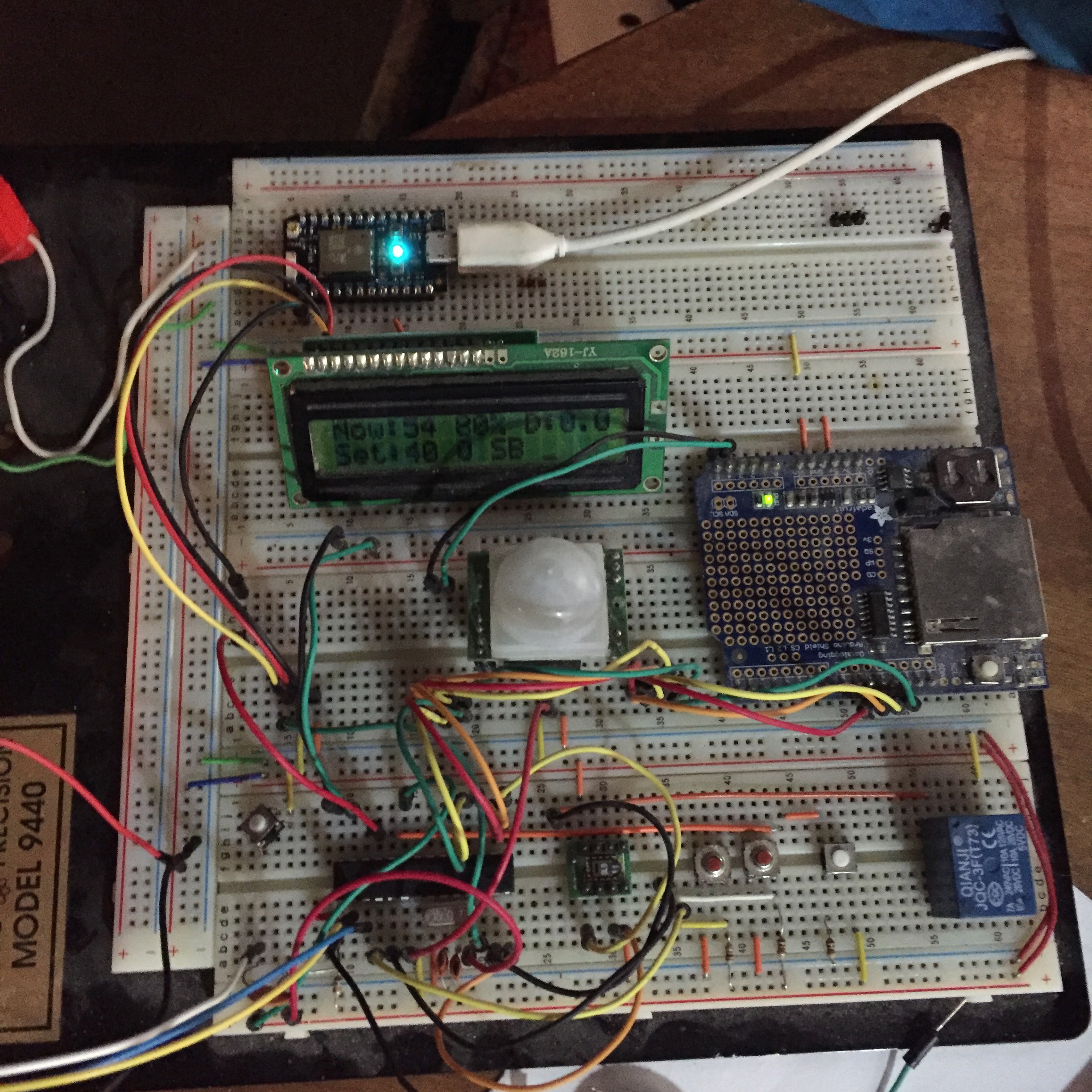
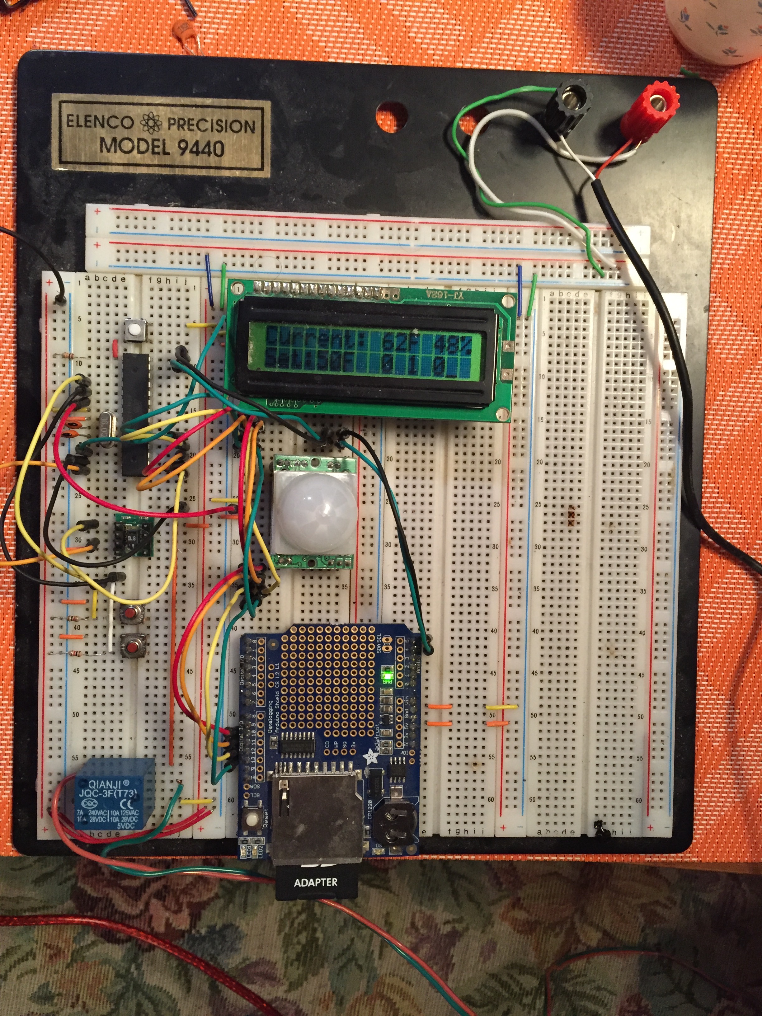
Yes (and I’m happy to see you). The Particle Photon is a programmable wifi microcontroller. The version 2 update included the Photon, but it only served as a link to the internet for basic control and minimal monitoring. The system still ran on the Arduino platform. Now, the Photon runs 100% of the system, and the Arduino has been phased out. This gives me full control, and full monitoring capabilities.

Don’t Blynk, you may miss it.

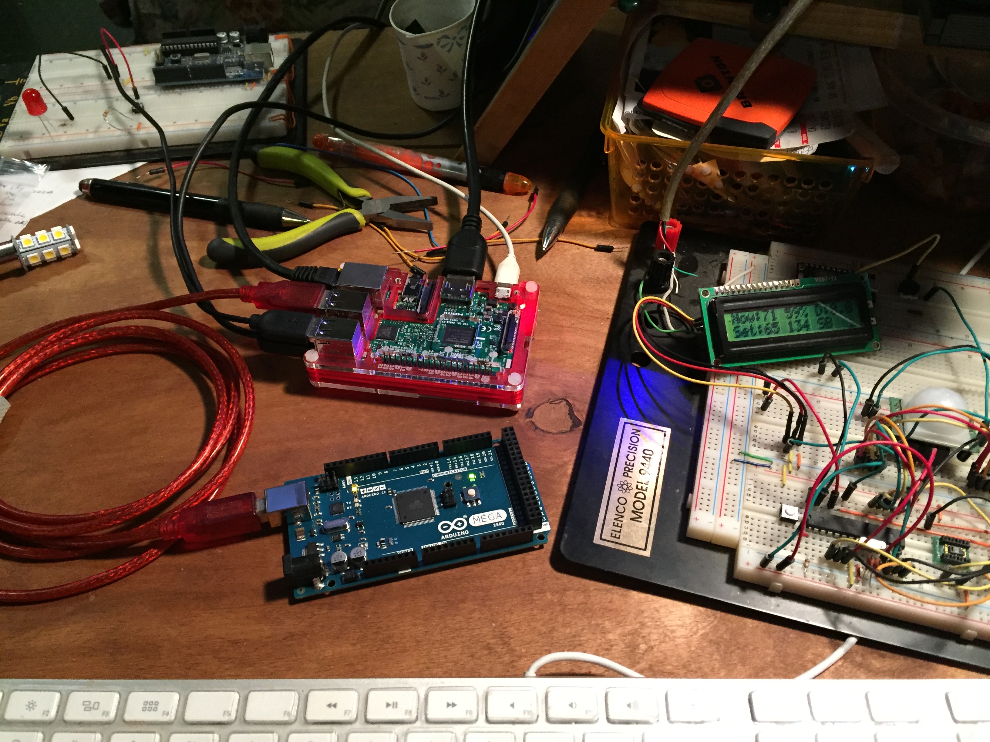
Blynk is an app that allows you to communicate 
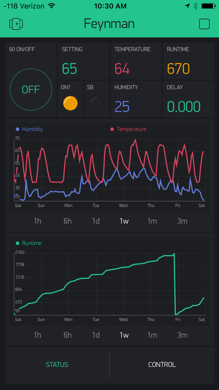
with your microcontroller projects. It works with a number of popular platforms. You can read data from your hardware to keep tabs on it, or you can write data to the hardware to control it. It is very simple to set up, and has proven quite flawless. As you can see in the pic, I am monitoring temperature, humidity, and furnace runtime. This data is also being graphed. The graphed data can be output to a csv file as well.

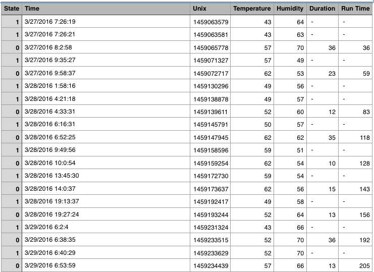
I’m also using Thingspeak as a primary means to log data for analysis later. There is a graph at the end of this post. It it one of the live feeds from the system to Thingspeak. You can see the whole public feed here.

Alexa, I’m freezing my testicles off.

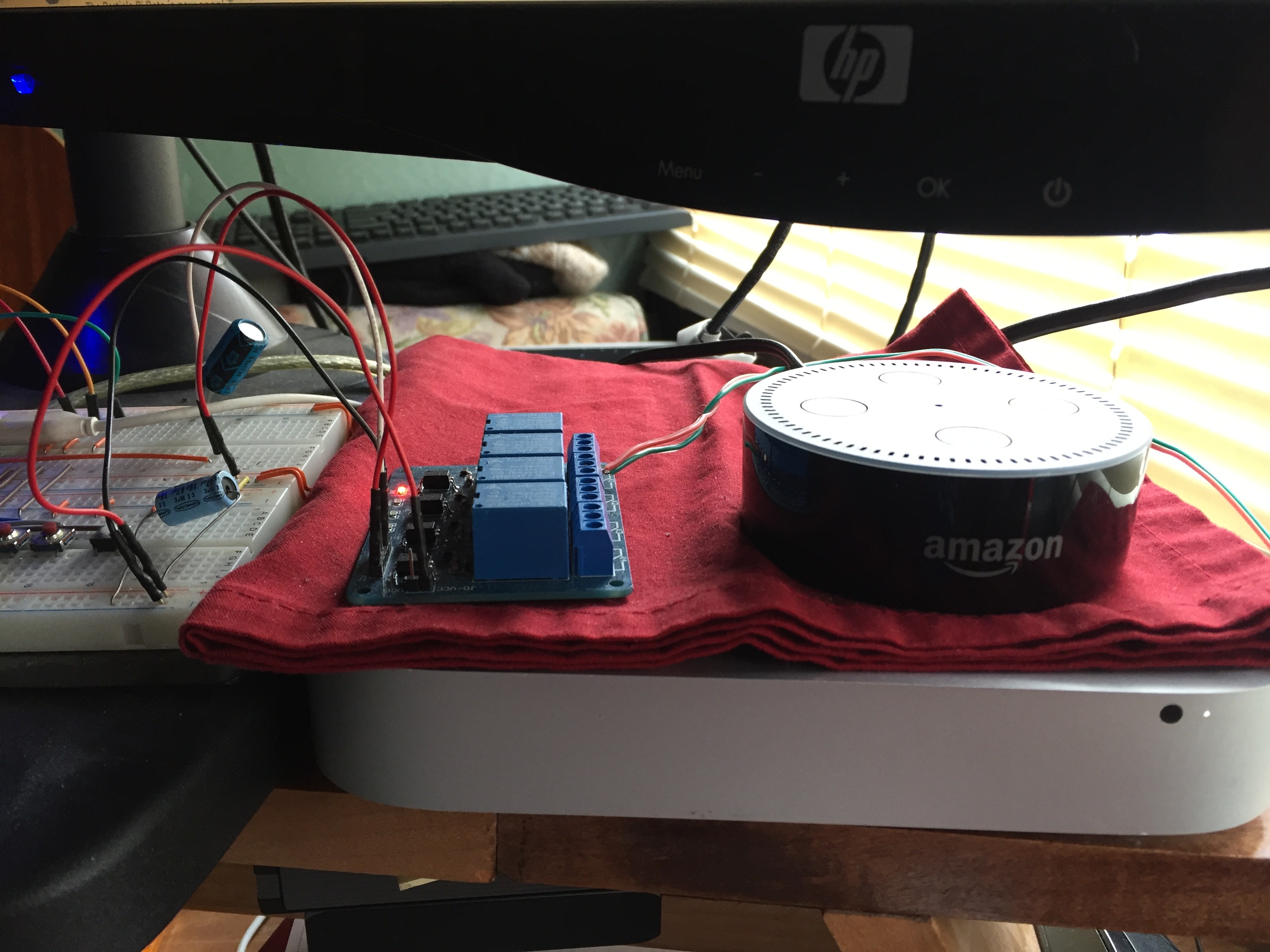
I have incorporated an Amazon Echo Dot into the equation, using the IFTTT service to link everything together. I can tell the Echo to turn the furnace on or off, and trigger it to certain temperatures. You can’t use IFFFT to send variables, so I can’t pick any random temperature, the control has to be pre-defined. I had to write a function for 65°F, and one for 70°F.

Look, Ma, no hands!

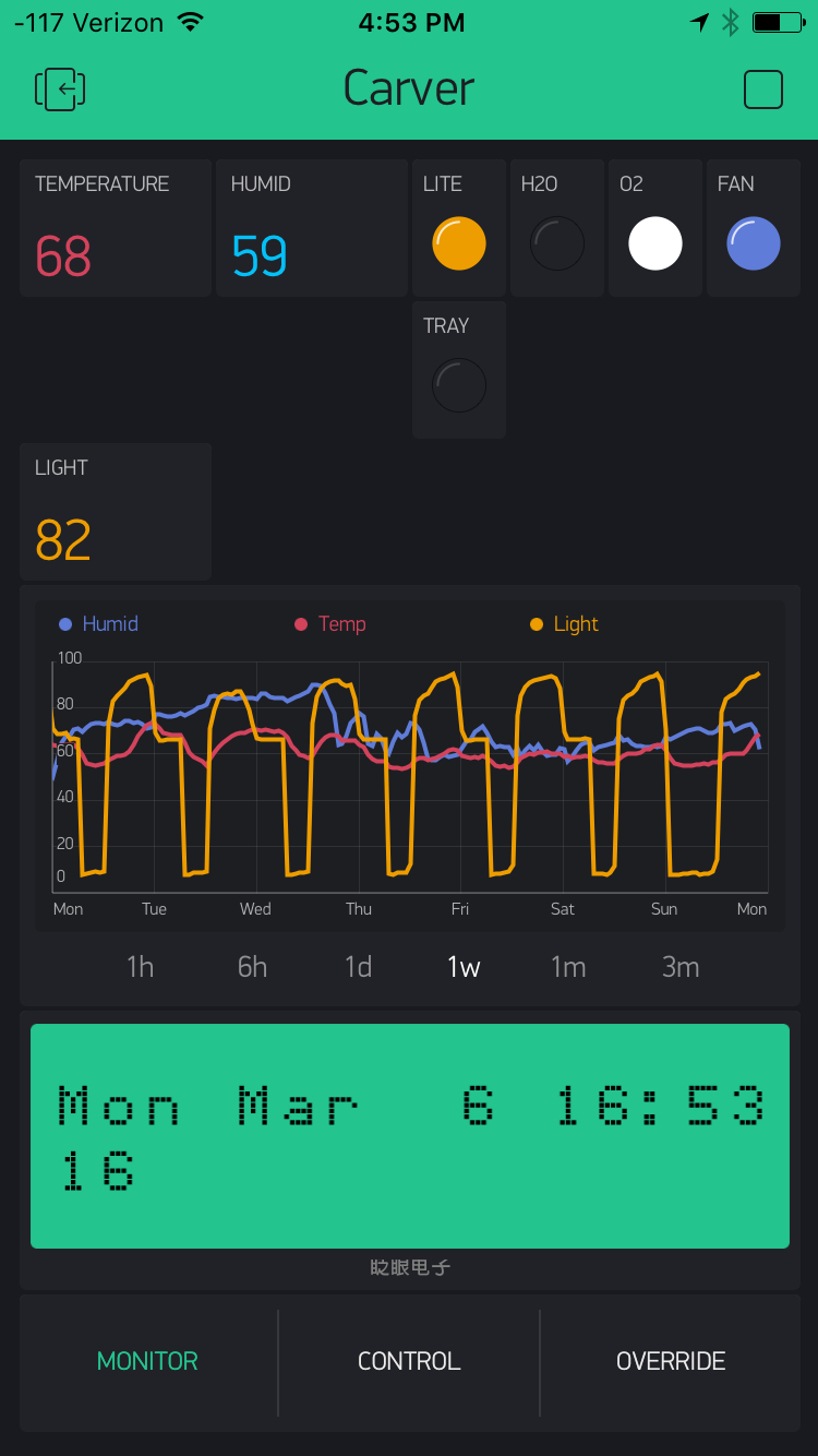
Between the Blynk app, and the Echo/IFTTT integration, the system runs without me ever actually interacting with it. I rarely ever use the buttons on the physical interface. The delay function I added in V2.0 was recently incorporated into the app. I also added indicators for the temperature setting and the standby status, which makes it more clear that the system has responded to my remote commands.

This is crazy, but here’s my number. Text me, maybe?

The IFTTT service is also set up for texting. I can text it an ON command, or a specific temperature. It will respond to confirm the action. The system will also text me if the temperature drops below 38°F, because that means that my propane tank has run empty (Yes, that has happened when I was gone overnight. Yes everything froze. Luckily, nothing was lost. My water system thawed out and worked fine). The IFTTT service limits you to 100 texts per month, so you have to be mindful of when you use that type of notification. My 38° notifications (being high priority) are quite incessant, and come in waves that will quickly trip that threshold.

A day in the life.

So here’s what a typical day might look like. Before bed, I will determine what time I plan to wake, and set my delay for one hour earlier. Then I tell the system to turn off and crawl into my sleeping bag. The temperature is allowed to drop to 40°F overnight. When I wake up, the system will have been on for an hour, and it will be close to 60°F. I tell it to turn off before iI leave for work. If I forget, the motion sensor will do it for me after an hour. Before I leave work for the day, I’ll will check in. The system will be in standby mode (40°F) since there has been no motion for over an hour. When I hit the ON button, I can clearly see the system come out of standby mode, set itself to 60°F, and turn on. I can also set a specific temperature, if required. When I get home, it’s nice and toasty. Lather, rinse, repeat.

Thanks for reading. As a parting gift, enjoy this live graph of the temperature in the camper. It updates every 2 hours. (I’m no longer using Thingspeak, so this graph is no longer a live feed).

The RoboGarden or, “Do Android Cukes Dream of Electric Salads?”

Garden Brain
This is Carver, the brain.

I’ve been so busy DOING this project that keeping updates here has eluded me. I had previously written about the Food Computer concept being deployed by the MIT Media Labs Open Agriculture Initiative. I was keeping an eye on the progress over there, intending to build one of their systems. I decided to temporarily “do my own thing” for a couple of reasons. For starters, their system is in development, and jumping in now requires a level of knowledge that escapes me. I’m just not up to speed on the level of software development required to use their approach right now. Second, I have decided that building my own setup based on a traditional hydroponic system has more value and efficiency for me at this juncture. I eventually hope to have a system that is 100% compliant with the MIT approach, so I can contribute to the data gathering, educational, and community based initiatives they are so gallantly spearheading.

So, why go your own route? 

As I mentioned, my software development abilities drift far behind my hardware abilities. I am a bit lost looking upon the sea of code that MIT has out there. I have already put a number of the pieces together in preparation, but I knew my own approach would be a less frustrating way to actually get results. Reason number two is cost. By some estimates, the food computers can quickly run between $2,000 and $3,000 (depending on who you talk to and what materials you source). I have a currently running system that has cost me $1000 to date, and is just about to produce food. A third reason is the systems footprint. My system has about 4 times the grow area of a standard food computer (in fact, my system is almost better described as a “food server” in some regards). This means I can grow an actual useable crop. The standard food computer is a great opportunity to experiment, but the actual output would be pretty low as far as trying to feed myself. And thats my fourth reason, feeding myself. I have a lofty goal that someday I will grow 100% of my own food, so this is a step toward that goal (especially in the winter). I don’t eat meat, so veggies are the only thing I need to produce. Those of you that follow this blog will say “Hey, didn’t you write about eating the squirrels that plagued your camper?“, and you’d be right! Well, that was then, this is now, get over it (smiley face). Of course, going my own way has some disadvantages.

What are these disadvantages of which you speak?

Well, many of the problems have yet to surface, I’m sure. I’m on my first crop, so I have no idea what the final results will be. Will I get fruit at all? Will it taste like cat food? Who knows. A big problem is that my system is just one large system with one climate, one light cycle, and one nutrient spread. I have to be cautious what array of seeds I plant. If they require different nutrients or lighting,  or have vastly different timing of growth stages, or different tolerances of heat, humidity and pH, it just won’t work. My idea of a constantly rotating crop (eating one crop while starting a new one) is likely to be impossible. I may have to do one crop, can/freeze/preserve it, and move to the next. Perhaps I will reserve its use to crops that cannot grow in my difficult climate, and stick to soil for others. It’s a lot of question marks that will only be answered with time and results.

The most important disadvantage is that my system limits the data and knowledge I can contribute back to the MIT project, which is open source. Wanting to support their open source initiative is my motivation to push myself to build a proper food computer ASAP.

Blynk App
Remote monitor and control courtesy of the Blynk App

Cool story, just tell us about your setup already.

So it’s built with the Particle’s Photon microcontroller. It uses a temperature/humidity sensor (an AM2315), and a simple LDR to sense light levels. There is a propane furnace keeping it warm in our sub-zero temperatures. The brain (pictured above) uses a bank of relays to control two dual gang outlet boxes. The left 4 outlets are individually switchable, while the right are switched in pairs. This controls all of the pumps and lights and fans.

My code tells everything when to turn on and off. It can be overridden and manually controlled using an app called Blynk that talks to the system remotely and also allows me to monitor from afar. It texts me when the temperature drops low, alerting me to change the propane tank. That’s all setup using IFTTT.

In terms of hydroponic style, it’s a flood and drain system. The pump runs long enough to fill my tray, which then drains back to the holding tank. This keeps the roots wet and oxygenated. The water has a nutrient solution balanced for the needs of the plants. The water is oxygenated with a pump, much like a fish tank is. The pH is controlled via application of acids/bases depending on careful readings from a meter. I’m using a Hannah 98129 Combo meter that tests pH, Conductivity (EC), and Total Dissolved Solids (TDS). My grow light is an 8 tube, 40,000 lumen, T5 fluorescent unit by Agrobrite.

Transpalnt
Operation Transplant

I started seeds on 1/20/17. By 1/31/17, I had seedlings ready to transplant. The seeds were started in rockwool cubes. The seedlings (cube and all) were then transplanted into net pots filled with an inert clay substrate. Every hour, the tray floods and drains. The light initially stayed on for 18 hours a day. Today, that changed to 12 hours a day. This is interpreted by the plants as the days getting shorter. It’s their cue to start flowering and producing fruit.

growth progress
Salad O’clock?

When my cucumbers began to reach out vines, I set dowels out to catch them, but today I switched that to a net trellis. I also switched my nutrients to a flower/bloom friendly variety. As you can see by the picture, I have come a long way from seedlings.

As always, anyone who would like to build something like this is welcome to my code, which I will probably place on GitHub at some point. Just email me from the contact page. I’ll write more when I start seeing fruit.

Nerdfarmers unite!


Enter, The Food Computer


openaglogowhite_small2The coolest part of my trip to the White House was the discovery of the Food Computer. This device is the small scale prototype for a much larger project taking place a the MIT Media Lab. It’s the work of Caleb Harper who is behind MIT’s Open Agriculture Initiative. The project has several aims. Ranging from educating kids about food (where it comes from, how it grows, etc…), researching how to grow better food, and of course, feeding people.


pfc_2
Caleb’s PFC hardware guts

Enter, the Food Computer

The PFC (Personal Food Computer) is the open source hardware and software system being developed to help change our food future. In layman’s terms, it is a system that controls all aspects of the plants environment over its whole lifespan. Since different plants have different requirements, the system uses a “climate recipe” (which is simply a series of instruction for the computer) designed the plant in question. Basically, you plant a seed (or a started seedling), select the climate recipe, and press play. The machine will maintain the right temperature and humidity, it will provide the proper nutrients, it will cycle the lighting, it will do everything the plant needs. Then you eat it.

pfc-parts
My Raspberry Pi and Arduino getting set up for growing.

How does it work?

So, as you might expect, it’s a bit more complicated. There is quite a lot going on under the hood. Here’s bit of geek-speak; It uses a Raspberry Pi as it’s brain, and an Ardunio Mega for the heavy lifting. The Arduino controls the mechanical bits like pumps, and relays, and monitors the array of sensors. The sensor data is passed to the Pi where the climate recipe can tell the Arduino when to perform necessary functions. For example, a pH sensor tells the system when to raise or lower the pH, and a peristaltic pump can supply a solution to make that change. It also does this with the nutrient solutions electro-conductivity, among other things. You can control CO2, Dissolved Oxygen, and nutrient solution temperature. So, the pant receives everything it needs, precisely when it needs it, (ideally) without human intervention.

pfc_1
Caleb’s PFC at SXSL growing basil

As we speak (December 2016), the PFC V.2.0 is being released. The original version was more difficult and expensive to build. V2.0 is working to change that. It’s an alpha release right now, so there is still work to be done to make it as cheap/easy/accessible as possible. Being open source, anybody can download the plans and the software to build one. You can contribute your ideas to make it better. The release of the plans is an ongoing process, so don’t expect a simple plug and play approach just yet.

So where is this headed?

As the PFC becomes more accessible, more people will build them (including schools, some are already doing so). The plan is to make kits available for purchase to simplify the part sourcing. As the user base increases, a database of climate recipes will amass. You can download a recipe that suits your needs, or you can experiment and upload your own results for others to use.

Whats really exciting is the opportunity for knowledge. Caleb described to me how his team freeze dries the resulting plants and places them in a spectrometer to see the nutrient/chemical break down. They can change growing variables and see the direct results of those variables on the plants chemistry. They can stress the plant in very specific ways (light or nutrient starvation, bacteria introduction, pH/EC shifts) to see what chemical defenses it puts up, and how that changes the nutrient/chemical properties. These things affect the flavor, the nutrition, the shelf life, etc… The best part is, IT’S ALL REPEATABLE. A good result can be downloaded and recreated by anyone, anywhere, with a PFC.

Food Servers and Beyond

The PFC is admittedly small. You aren’t going to feed your family with it. It’s footprint is about 3 feet wide by a foot and a half deep, and it stands maybe 3 feet tall. It could fit on a counter or a small table, and can grow about 4 small plants at a time. But the PFC is simply the home version of what MIT is really building at OpenAg. The PFC is like a test platform to get us geeks involved and improve the system. The lessons learned in the small scale are being put to use in Food Servers. The servers are built in shipping containers, using the same hardware and software. This is all happening now, in the new lab that OpenAg has just opened. The next phase is the Food Datacenter, which scales the project to warehouse size. The scalability is built into the project, so it’s instantly scalable without having to be reimagined.

Servers and Datacenters can be deployed in various ways. They have a home in climates that don’t support standard agriculture, they have a home where food is scarce and people are hungry. In America, they have a home in the city. According to the census bureau (in early 2015), 62.7% of our population lived in the city, and cities make up 3.5% of our land. The food to feed our population often travels an enormous distance. The urban agriculture push seeks to change that. We see more city gardens and roof gardens, but it’s not enough. There is talk of entire floors of skyscrapers becoming farms. This is where food computers can play a role.

So what is my plan?

I am WAY into the whole food computer concept, and I hope to contribute to the initiative ASAP, but I am financially challenged. They are working hard to make a system that is affordable to build, but obviously this system will presumably lack some of the higher tech solutions that MIT is deploying in their own systems. I’m keeping my eye on their progress, and buying what I can, when I can, in order to deploy a PFC. But I’m not spending my time idly, I’m building my own hydroponic system.

Armed with a prime directive of feeding myself, the PFC is taking a necessarily secondary position, but I’m keeping it’s spirit nearby. The systems I’m designing to control my growing environment are taking their cues from the PFC. I’m trying to keep my equipment selection to PFC compatible options. Eventually, I hope my system will run on the food computer software. In that sense, I’m skipping the PFC and going straight to the food server, though I do plan on having a dedicated PFC as well.

I already have about 80% of my hydroponic operation setup, and hope to be starting seeds by the end of the year. Naturally, I will be writing about the journey as it unfolds.

Keep making stuff (and remember, growing food counts as making stuff!)


Thermostat Update V2.0

img_1355UPDATE: Version 3.2 is live. Read about it HERE.

This is just an update on some thermostat happenings of late. I recommend reading the original post to get up to speed.

DELAY CIRCUIT

I have mentioned elsewhere that I maintain a temperature of 40°F overnight while I sleep. I find that to be a great temp for sleeping, and for saving on propane. It’s a bit rough for getting ready for work in the morning, though. I tried keeping it at 50°F overnight when I started getting a steadier income, but realized just how much propane it takes to get an extra 10 degrees. I decided to add a delay function to the system. I did not want to futz with the complexities of a programmable timer circuit, especially since the RTC chip is not known to be super accurate. I decided a simple delay was best. It’s just a button that increments a delay time. I set the delay for, say, 7 hours, and go to bed. When I wake up the furnace will have been running for about 30 minutes, and its good and toasty.


REMOTE (WEB) CONTROLimg_1320

I had always planned to introduce the thermostat to the Internet of Things, and finally made that happen this weekend. I’m still debating on my final approach, but for now, Ive gone with the Photon from Particle.  It proved to be a REALLY fast and SUPER EASY platform that saved me a TON of headaches and development. No hosting a local web server, no port forwarding, no dynamic DNS. Almost plug and play! I have a lot more work to do. The interface is virtually non-existent besides a simple on/off. I want to get some feedback from the system, like temperatures and runtimes. The problem is the difference in logic level. The Atmel chip uses 5V logic, the Photon uses 3.3V. Luckily, 3V is the threshold for the Atmel pins to go HIGH, so the Photon CAN trigger the Atmel chip. But I can’t safely send any info from the Atmel to the Photon without damaging it with 5v. I’ll be getting some 74 series level shifting DIP chips soon, but until then, I going build a simple voltage divider to tide me over.


My eventual plan is to have my Raspberry Pi operating as the brain of the camper, controlling all the sub systems though a web interface. I’ve gotten as far as running Apache and PHP on my Pi, but its the old (orignal) Model B, and I think I’m due for an upgrade. I’ll write again when the web interface is complete. Keep making stuff!


The Jedi Light Trick

img_1353

I have grand schemes on setting up a solar powered LED lighting system in the camper, but until the money and motivation magically align, i’m just making it up as I go. All of the light fixtures in my camper are old and cracked and falling apart. The central most light fixture died completely recently, and I made do without it until now. Years ago (January 2012) I built an infrared light switch (programmed with Arduino and housed in an Altoids tin) to control some halogens I no longer use. I stumbled across that old circuit today and decided to repurpose it. I wrote about the original build back then, if you care to read the details. It has the schematic (EagleCAD) and Arduino code attached if you want to build your own. My dad (who is obsessed with LED lighting) had just given me a neat 12V LED array to check out. He is always finding cool lights like this on eBay.

The circuit is powered with 12v because it uses a 12V relay, which was all I had on hand the day I built it. I’d like to redo it with a 5V relayimg_1346 since that is all the Atmel chip needs to operate. 12V poses a couple of problems. First, since the chip requires 5V, I have to step the voltage down (with a 7805 in this case) which is not very efficient. Second, the Atmel chip cannot switch the relay on its own. The voltage/current is just too much. So I had to use an NPN transistor to switch to relay on. The chip switches the transistor, which in turn energizes the relay. I wasn’t really in the mood to re-solder a different relay in, and then have to re-write any code, so I left it as is for now.

img_1354It’s all programmed with Arduino. Its quite simple code wise, with about 40 lines of actual code. It really just monitors the iR detector for light reflected from the emitter (from a hand for example), and toggles the relay on and off when it sees it. The lights ground is switched via the relay. It was tricky to get the sensitivity right, as I recall. I thought I was going to build a ton of things into Altoids tins, but as yet, this is the only one.

The switch is located near the entry door. When I come home in the dark, it just takes a Jedi style hand gesture and the centrally located light will illuminate. I may be up to some solar and lighting projects in the near future, so stay tuned. Enjoy the included video, and see the link above for the circuit details from the original build post.


Keeping Warm, Part One: My Thermostat

IMG_0833

UPDATES:

See Version 3.2 HERE

See Version 2.0 HERE


Now that the northern Maine temperatures have finally crept above 40°F on a regular basis, I decided it’s time to talk about how I managed to stay warm this past winter. I’d like to start things off with my thermostat. There is a lot to say here, so i will devote the whole post to it. Other cold beating techniques will be discussed in part II.

Why Build a Thermostat?

“You know, you can buy a digital thermostat at Lowes for $17?” I got some version of that response from almost everyone I spoke to about my idea of building my own. The thermostat that came with my camper was working just fine. I didn’t need to build one, I wanted to build one. I take great pleasure in making things that solve a problem, and my DIY thermostat had the potential to solve a number of problems.

The first problem it solved was saving me $17. Everyone was right, I could just by a thermostat. At the time, Lowes had a basic digital Honeywell thermostat for $17. At the same time, I was broke, and $17 buys an epic amount of ramen. My geek stash had all of the bits and pieces I would need already, so there was no expense incurred in this project. The cost of propane was a big concern for me. I decided I needed to maintain a minimum of 40°F. Warm enough to ensure my water didn’t freeze, but cold enough to conserve on propane. My analog thermostat only went as low as 50°F, and “OFF” was so close to 50°F that I could never be sure if it was on 50°F of off completely.

Some higher tech solutions were deployed for extra geek cred. I knew I would forget to turn the temperature down before I left for work sometimes, so I used an infrared motion sensor to tell whether I was home or not. I wanted to gather data regarding how long, and how often my furnace ran. It would give me a gauge on how many hours of run time I could get out of a tank of propane. I used a data logger to write data to an SD card for later science.

How it Works

I’m going to try my best to keep it as layman as possible for the electronically uninitiated, but I will include some gritty details later to appease the electron junkies in the pack. This whole system is run by a microcontroller. Think of it like the processor (CPU) in your computer or whatever device you’re using to read this right now. All of the code that makes up the software you use is just a series of instructions that is read and executed by the CPU. So, I write some code, load it onto the controller chip, and it runs the program over and over. In this circuit, there is a temperature and humidity sensor. The controller constantly asks the sensor what the temperature is. I set my desired temperature by using two buttons to bring it up or down. When the temperature reported by the sensor is lower than the temperature I set, the code turns the furnace on. It’s more complicated than that, but that’s the basic idea. The controller also uses the infrared sensor to check for motion. If it sees no motion for an hour, it goes into a 40°F standby mode. Any time the furnace turns on, that event is logged to the SD card, including the time. When the furnace turns off, that event and time is logged as well. The times are subtracted from one another to determine how many minutes the furnace ran. That time is added to a cumulative run time.

The Geek Stuff

Here is some jargon. Feel free to skip this paragraph. This was programmed using the Arduino environment, but in a standalone arrangement (the controller runs on its own, without the support of the programmer). I’m using an older Sensiron temp/humidity sensor, and Adafruit’s Datalogging Shield. All of the pertinent info is written out to a Parallax 2×16 LCD. The furnace turns on with a contact closure, which is achieved by energizing a 5V relay. There is a mix of both i2C and SPI serial communications. The Sensiron chip uses i2C, the data logger uses BOTH protocols (i2C for the onboard RTC chip, and SPI for the SD read/write operation). I’m happy to share my code with anyone interested, but I’m not sure how compatible it is with more modern temp sensors.

thermologThe Numbers

I lucked out, because we had a very mild winter. The lowest temperature I saw was -16°F  (our wind chills brought us down to -30°F once in a while, but not often). I only spent $300 on propane all winter, and I was expecting much more. Each 20lb propane tank gave me over 30 hours of burn time depending on how much I was cooking (the stove uses the same propane). The spreadsheet on the left is a screen grab of the CSV file as it is written to the SD card. By keeping the temp at 40°F while sleeping or when I was gone, I saved a buttload of money. It took an exceptional amount of additional propane just to try to maintain 50°F overnight. Sleeping at 40°F was quite pleasant. A good sleeping bag is the only prerequisite. Getting ready for work in the morning is NOT quite so pleasant at 40°F, but I wasn’t expecting this to be easy.

Conclusion

What I really love about this process is the troubleshooting aspect of problem solving, and what I learn as I navigate it. Reality never behaves the way our ideas do on paper, and the act of wrapping our brains around those surprises teaches us a lot about the world. Sometimes, something seemingly so simple is actually far more complex. Sometimes, very complex things have very simple answers. I assumed that my code could say “when the temperature hits 60°F, turn the furnace off.” But in reality, the temperature fluctuates a lot as the room seeks equilibrium. The furnace would turn on and off several times while this happened, and it was hard on the electrical system. I had to write code that held the furnace on through a “buffer” period to let the room stabilize, and that minor change took more thought to engineer than the whole system did.

When we finally hit a warm spell, my furnace died! The timing couldn’t have been any better. It would have been an outright calamity even a week before. I had just made $80 helping my Mom out, and the part I need to fix the furnace happens to cost $80. Oh, how kind the universe can be when I don’t get in the way. In part two, we’ll talk about clothing, and the dynamic nature of human comfort.

UPDATE: I’ve added some features! See Version 2.0 HERE